Motor Control using PWM and PID
 Bi-directional motor control can be done using an H-bridge circuit
with pulse-width modulation (PWM) from a microcontroller to vary
the speed. Several design challenges include preventing shoot-through, implementing
a snubber circuit, as well as open and closed loop (such as PID) control
mechanisms.
Bi-directional motor control can be done using an H-bridge circuit
with pulse-width modulation (PWM) from a microcontroller to vary
the speed. Several design challenges include preventing shoot-through, implementing
a snubber circuit, as well as open and closed loop (such as PID) control
mechanisms.
PWM Control of an H-Bridge
An H-bridge circuit consists of four transistors (usually two PMOS’s and two NMOS’s). To maximize efficiency, the transistors are driven at a higher voltage than the microcontroller. A typical H-bridge circuit with logic scaling circuitry is shown above.
Each side of the H-bridge has two transistors with the gates tied together resulting in complementary operation–Q3 is always off when Q1 is on and vice versa. The same is true for Q2 and Q4. The circuit works by setting PWMB to logic zero (Q2 on; Q4 off) and then setting PWMA to logic high (Q1 off; Q3 on). The motor direction can be reversed by toggling PWMA and PWMB.
The H-bridge uses NMOS and PMOS resistors in a complementary fashion. In the logic world, this is known as CMOS circuitry. Most logic gates are designed using NMOS and PMOS in a complementary way. Our How Microcontrollers Work post illustrates how to use NMOS and PMOS transistors to build logic gates such as NOT, AND, OR, etc.
PWM is a simple way to vary the voltage applied to the motor. Most microcontrollers have dedicated PWM hardware, but an output compare timer can also generate a PWM signal. PWM works by rapidly turning the motor on and off. For example, if the motor supply is 12V, the motor can be driven at 6V by applying a 50% duty cycle where half the time 12V is applied, and half the time 0V is applied as shown by the green signal in the plot below.

While using PWM is simple, it introduces a problem called shoot-through which occurs when current flows directly from the power supply to the ground when the transistors are being switched. For example, when the PWMA input signal switches from high to low, Q1 turns on and Q3 turns off. For a brief period, both Q1 and Q3 are partially on allowing current to flow from the supply to the ground. This causes efficiency to plummet and introduces heating problems in the transistors. To overcome this problem additional circuitry must be added to ensure Q3 turns completely off before Q1 starts to turn on.
Preventing Shoot-through
The easiest way to implement a shoot-through prevention circuit is to use an integrated circuit (IC) that has shoot-through protection built-in. The Si9986 IC from Vishay is an H-bridge motor driver circuit with built-in shoot-through protection as well as logic translation circuitry (Q5A and Q5B in the diagram above). It is a great solution for controlling a small DC motor using a PWM signal from a microcontroller. When using the Si9986, as with using any motor driver, a snubber circuit is required to reduce electromagnetic noise in the system.
A Snubber Circuit to Decrease Noise
A snubber circuit is used to suppress the voltage transients caused by PWM switching (as well as by the inherent switching in brushed motors). A DC motor is an inductive load; the voltage across it is proportional to the change in current, given by:
$$ V_L = L \frac{di}{dt} $$
When the PWM signal switches the motor from on to off, there is a rapid change in current (ie di/dt is large) which causes a voltage spike. Without a snubber circuit, the energy from the voltage spike can result in arcing, damage to the body diode in the H-bridge transistors, or cause electromagnetic interference in nearby circuitry. The snubber circuit safely dissipates the energy in passive elements. A simple, effective snubber circuit consists of a resistor and capacitor in series across the terminals of the motor as shown below.

PID Control
With an H-bridge, a pair of PWM signals, and a snubber circuit, the motor is ready for bi-directional control. The simplest form of control is an open loop. This means the controller simply applies a voltage (a PWM signal in this case) but has no way to measure the effect of the applied voltage. The controller simply assumes higher voltage makes the motor go faster. Closed-loop control uses feedback from the motor, such as the motor current or speed, to adjust the PWM signal.
A PID loop–verbosely known as proportional, integral, differential loop–is a popular algorithm in many closed-loop systems.
PID loop

Image from Wikipedia
The diagram above represents a PID-controlled process. In this case, the “process” or “plant” is the motor. The feedback mechanism–y(t) called the process variable–can be either the motor current or speed. The setpoint, u(t), is the desired current or speed. The PID loop takes the difference (or error), e(t), between the setpoint and the process variable, applies namesake adjustments–proportional, integral, as well as differential–and then sums the result to get the new value of the manipulated variable (the PWM duty cycle).
The following code is a PID loop implementation using floating-point variables. The structure (pid_f_t) is first initialized using pid_init_f() with the minimum and maximum values for the manipulated variable accepted as parameters. The minimum is useful if the motor requires some minimum PWM duty cycle to make it turn while the maximum ensures the PID algorithm does not try to exceed 100% duty cycle. The pid_update_f() function uses the current setpoint and the process variable as well as the constants stored in the pid_f_t structure to compute the manipulated variable. The application loop includes a function to measure the motor current or speed, call pid_update_f(), and set the PWM value according to the manipulated variable.
The Stratify API calc::Pid_f class is a C++ implemenation of a PID loop on boards power with Stratify OS. There are additional code references on Github.
typedef struct{
float max /*! Max manipulated value */;
float min /*! Miniumum manipulated value */;
float e /*! Error value */;
float i /*! Integrator value */;
float kp /*! Proportional constant */;
float ki /*! Integrator constant */;
float kd /*! Differential constant */;
} pid_f_t;
/*! \details This function initializes the data in a PID structure.
*
*/
void pid_init_f(pid_f_t * ptr /*! A pointer to the PID data structure */,
float min /*! The manipulated variable's minimum value */,
float max /*! The manipulated variable's maximum value */){
memset(ptr, 0, sizeof(pid_f_t));
ptr->min = min;
ptr->max = max;
}
/*! \details This function updates the value of the manipulated variable (MV)
* based on the current state of the PID loop.
*/
float pid_update_f(float sp /*! The set point */,
float pv /*! The process variable */,
pid_f_t * ptr /*! A pointer to the PID constants */){
float temp;
float e;
float p;
float manp;
float tmpi;
e = ptr->e;
ptr->e = sp - pv;
tmpi = ptr->i + ptr->e;
//bound the integral
manp = ptr->kp * ptr->e + ptr->ki * tmpi + ptr->kd * (e - ptr->e);
if ( (manp < ptr->max) && (manp > ptr->min) ){
ptr->i = tmpi;
} else if ( manp > ptr->max ){
manp = ptr->max;
} else if ( manp < ptr->min ){
manp = ptr->min;
}
return manp;
}
It is important to properly apply the manipulated variable to the process. In the H-bridge shown above, Q5 inverts the PWM signal which means the software needs to invert the PWM value before applying it. Also while switching Q2 and Q4, the states of Q1 and Q3 determine the motor direction; this affects how the sign of the manipulated variable is interpreted. These nuances in the circuit can make debugging a PID loop tricky but can be overcome with sound analysis as well as trial and error.
Example
Here is an example circuit and code using a microcontroller development board, a 12V DC motor connected to a rotary encoder, and the Si9986 H-Bridge driver chiThe image below shows the breadboard setup.
Hardware Setup
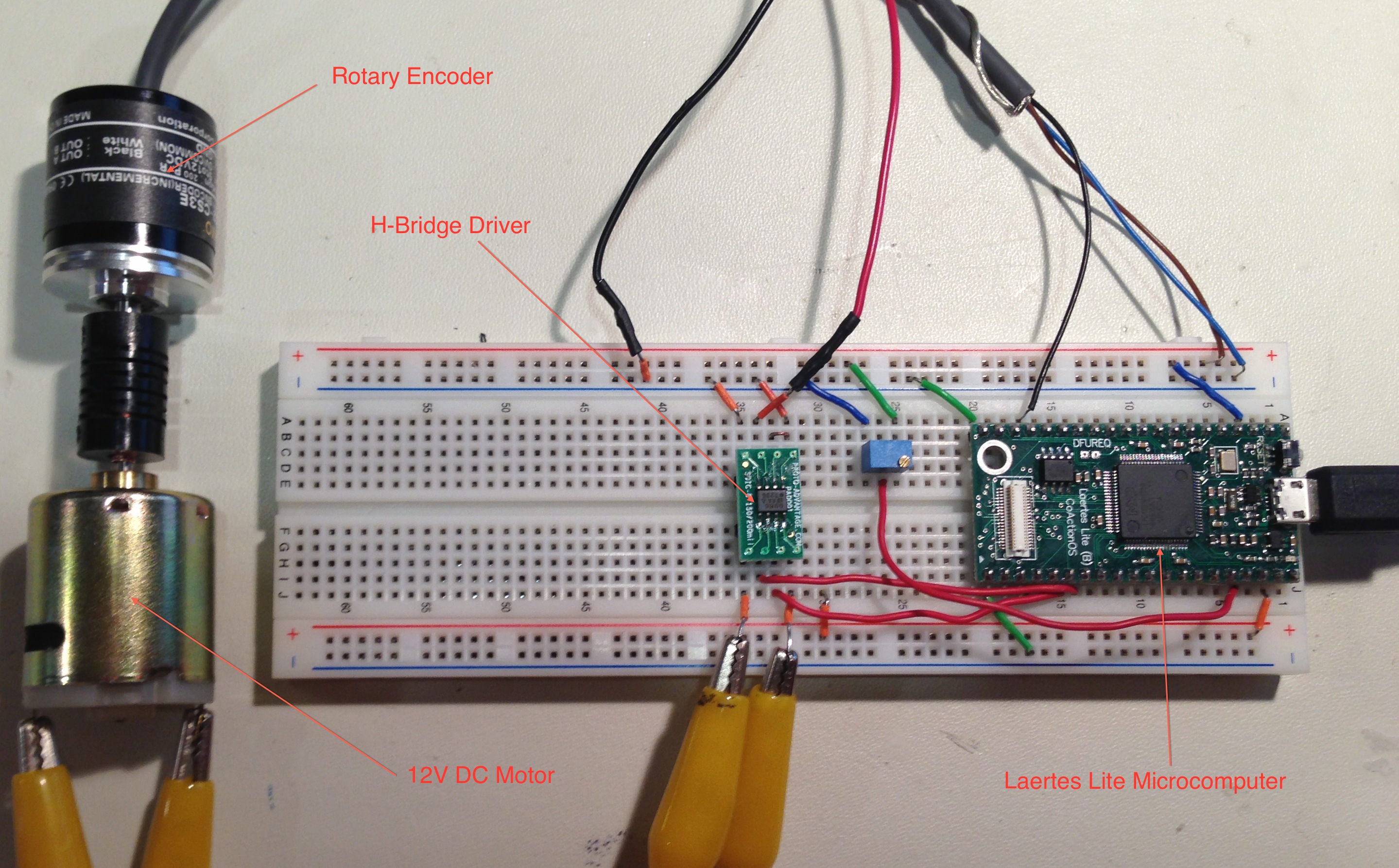
The parts include:
- Microcontroller Development Board
- SMT to DIP Adapter and Si89986 H-Bridge PWM Driver
- Generic 12V DC Brushed Motor
- Rotary Motor Encoder (200 counts per revolution from Sparkfun Electronics)
- 10K Potentiometer (used for user input)
The following drawing shows the specific connections. The user input (to set the speed) consists of a potentiometer wiper connected to P0.2 (ADC Channel 7). The rotary encoder is connected to P1.26 which also serves as a clock input for timer zero. Finally, 2.3 and 2.4 are PWM outputs connected to the input of the Si9986 H-bridge driver.

Source Code
The source code uses a PID loop to control the motor speed. First, it reads the ADC to calculate a speed setting from 1500RPM to 10,000RPM which is set by the user using the potentiometer. After the ADC is sampled, it is filtered using an exponential moving average, low-pass filter. This prevents noise on the ADC from causing changes to the speed setting. The code then calculates the motor speed in revolutions per minute. It measures the rising edges of the rotary encoder (200 counts per revolution) using the timer clock input. It then uses the POSIX function (provided by Stratify OS) clock_gettime() to calculate the change in time since the last measurement. The current speed is then the change in the number of revolutions divided by the change in time. The current speed and the setpoint speed are then passed to the PID calculation which returns the duty cycle which is applied to the PWM output.
#include <stdio.h>
#include <applib/pwm.h>
#include <applib/tmr.h>
#include <applib/adc.h>
#include <time.h>
#include <dsp.h>
#include <pid.h>

#define TMR_PORT 0 //Timer port used to capture encoder data
#define ADC_PORT 0 //ADC port for getting user input
#define ADC_INPUT_CHAN (7) //ADC channel for user input
#define PWM_PORT 1 //PWM port for Si9986
#define PWM_CHAN_HIGH (PWM_CHANNEL5)
#define PWM_CHAN_LOW (PWM_CHANNEL4)
#define PWM_FREQ (1000000)  //PWM clock frequency
#define PWM_TOP 1000 //Top value for PWM clock
#define PWM_PERIOD (PWM_TOP*1000/PWM_FREQ) //Period in ms

static int init(void); //initilize timer, PWM and ADC
static int init_tmr(void);
static int init_pwm(void);
static int init_adc(void);

//Set the output duty cycle
static void set_duty(int duty);

int main(int argc, char * argv[]){
  pwm_reqattr_t req;
  int i;

  //These are for sampling the ADC (user input)
  adc_sample_t samp;
  int32_t samp_avg;
  uint16_t alpha;
  uint32_t set_speed;

  //This is for measuring the motor speed
  uint32_t delta_ms; //elapsed time in milliseconds
  uint32_t last_ms;
  uint32_t now_ms;
  uint32_t ref_ms;
  struct timespec now;
  uint32_t current_pos; //current position
  uint32_t last_pos; //position from last measurement
  uint32_t delta_pos;
  uint32_t speed;

  //PID variables
  pid_i32_t pid;
  uint32_t duty;

  if( init() < 0 ){
                //exit unsuccessfully if any hardware failed to initialize
    exit(1);
  }

  //Initialize the ADC averaging (EMA filter)
  alpha = DSP_EMA_I32_ALPHA(0.1);
  adc_read(ADC_PORT, ADC_INPUT_CHAN, &samp, sizeof(adc_sample_t));
  samp_avg = samp;

  //Since there is no initial measurement, the first speed will be bogus
  last_ms = 0;

  //initialize the PID
  pid_init_i32(&pid, 200, 900); //Bound the duty between 20% and 90%
  pid_setconstants_i32(&pid,
                        //These constants take some tweaking to get everything to work smoothly
      PID_I32_CONSTANT(0.05), //P constant
      PID_I32_CONSTANT(0.01), //I constant
      PID_I32_CONSTANT(0.0001)  //D constant
      );

  usleep(50*1000);
  set_duty(0);

  //Get the initial time so that the program start time is close to zero in the output data
  clock_gettime(CLOCK_REALTIME, &now);
  ref_ms = (now.tv_sec * 1000 + (now.tv_nsec + 500000) / 1000000); //convert to milliseconds

  i = 0;
  while(1){
    //Read and averge the ADC to get the set point
    adc_read(ADC_PORT, ADC_INPUT_CHAN, &samp, sizeof(adc_sample_t));
    samp_avg = dsp_ema_i32(samp, samp_avg, alpha);
    set_speed = samp_avg * 8500 / ADC_MAX + 1500;

    //Now measure the position and calculate the speed (pos/time)
    clock_gettime(CLOCK_REALTIME, &now);
    now_ms = (now.tv_sec * 1000 + (now.tv_nsec + 500000) / 1000000); //convert to milliseconds
    delta_ms = now_ms - last_ms;
    last_ms = now_ms;


    current_pos = tmr_get(TMR_PORT);
    delta_pos = current_pos - last_pos;
    //calculate in RPM (1000*60 ms in a min and 200 counts per revolution)
    speed = (delta_pos*(1000*60/200))/(delta_ms);
    last_pos = current_pos;

    //Calculate the new duty cycle
    duty = pid_update_i32(set_speed, speed, &pid);
    set_duty(duty);

    //Display the data and wait for the next update
    if ( i++ > 0 ){ //first sample is garbage because the delta values are invalid
      printf("%d %d %d %d;\n", now_ms - ref_ms, set_speed, speed, duty);
    }
    usleep(25*1000); //update every 25 ms
  }

  return 0;
}

int init(void){
        if( init_tmr() < 0 ){ return -1; }
  if( init_adc() < 0 ){ return -1; }
  if( init_pwm() < 0 ){ return -1; }
  return 0;
}

int init_tmr(void){
  tmr_attr_t attr;

  //Open the timer port
  if( tmr_open(TMR_PORT) < 0 ){
    perror("failed to open tmr");
    return -1;
  }

  //We are using Capture 0 on timer 0 (CAP0. -- count rising edges
  attr.clksrc = TMR_CLKSRC_IC0 | TMR_CLKSRC_EDGERISING;
  attr.freq = 0; //this is not used with input capture counting
  attr.enabled_ic_chans = 0; //not used
  attr.enabled_oc_chans = 0; //not used
  attr.pin_assign = 0; //From the datasheet, this pin is using TMR1(0) where 0 is the pin assignment
  if( tmr_setattr(TMR_PORT, &attr) < 0 ){
    perror("failed to setattr tmr");
    return -1;
  }

  //Turn the timer on (start counting edges)
  if ( tmr_on(TMR_PORT) < 0 ){
    perror("failed to turn tmr on");
  }

  return 0;
}

int init_pwm(void){
  pwm_attr_t attr;
  pwm_reqattr_t req;

  //Open the PWM port
  if( pwm_open(PWM_PORT) < 0 ){
    perror("failed to open pwm");
    return -1;
  }

  //Set the PWM attributes
  attr.enabled_channels = (1<<PWM_CHAN_HIGH)|(1<<PWM_CHAN_LOW);
  attr.freq = PWM_FREQ;
  attr.top = PWM_TOP;
  attr.pin_assign = 1; //Using PWM1(1) from the datasheet the (1) means pin assignment 1
  if( pwm_setattr(PWM_PORT, &attr) < 0 ){
    perror("failed to setattr pwm");
  }

  //Allow the PWM clock time to initialize
  usleep(100*1000);

  //Set both PWM outputs to Zero
  req.channel = PWM_CHAN_HIGH;
  req.duty = 0;
  if( pwm_set(PWM_PORT, &req) < 0 ){
    perror("failed to set high duty");
  }

  req.channel = PWM_CHAN_LOW;
  if( pwm_set(PWM_PORT, &req) < 0 ){
    perror("failed to set low duty");
  }

  return 0;
}

int init_adc(void){
  adc_attr_t attr;

  //Open the ADC port
  if( adc_open(ADC_PORT) < 0){
    perror("failed to open adc");
    return -1;
  }

  //Set the ADC attributes
  attr.enabled_channels = (1<<ADC_INPUT_CHAN);
  attr.freq = ADC_MAX_FREQ;
  attr.pin_assign = 0;
  if( adc_setattr(ADC_PORT, &attr) < 0 ){
    perror("failed to setattr for adc");
    return -1;
  }

  return 0;
}

void set_duty(int duty){
  pwm_reqattr_t req;
  if( duty == 0 ){
    //This turns on the brake -- both outputs low
    req.duty = duty;
    req.channel = PWM_CHAN_HIGH;
    pwm_set(PWM_PORT, &req);
    req.channel = PWM_CHAN_LOW;
    pwm_set(PWM_PORT, &req);
  } else {
    //This runs in run mode -- one output is switching the other is high
    req.duty = PWM_TOP - duty;
    req.channel = PWM_CHAN_HIGH;
    pwm_set(PWM_PORT, &req);
    req.duty = PWM_TOP;
    req.channel = PWM_CHAN_LOW;
    pwm_set(PWM_PORT, &req);
  }
}
Results
To see how well the code works, the output is plotted against time using the following MATLAB (or octave) script.
output = load("log.txt");
plot(output);
xmin = min( output(:,1) );
xmax = max( output(:,1) );
ymax = 10000;
plot(output(:,1), output(:,2), output(:,1), output(:,3), output(:,1), output(:,4) );
xlabel("Time (ms)");
ylabel("Speed");
axis([xmin xmax 0 ymax]);
legend("Set Point", "Speed", "Duty*1000");
print("output.png", "-dpng");
The following shows the motor speed, duty cycle (per one thousand), and the actual speed.

To get the above performance, the PID constants required tweaking. The approach was to set the I and D values to zero and monitor the performance by changing the P value. Once a stable P value was found, the I value was adjusted to find a good trade-off between accuracy and stability. Finally, the D constant–the least significant in this application–was set.
Conclusion
Precision, bi-directional motor control is achievable in embedded designs using an H-bridge driver, circuitry to sense feedback from the motor, and a PID algorithm. It is important to have a well-designed H-bridge that prevents shoot-through and suppresses electromagnetic interference with a snubber circuit. The sensing feedback can come in the form of speed (using encoders) or current; though, the best results will be achieved using an encoder. Finally, the PID algorithm can be tuned to ensure the control algorithm meets the application’s requirements.