ADC Signal Conditioning
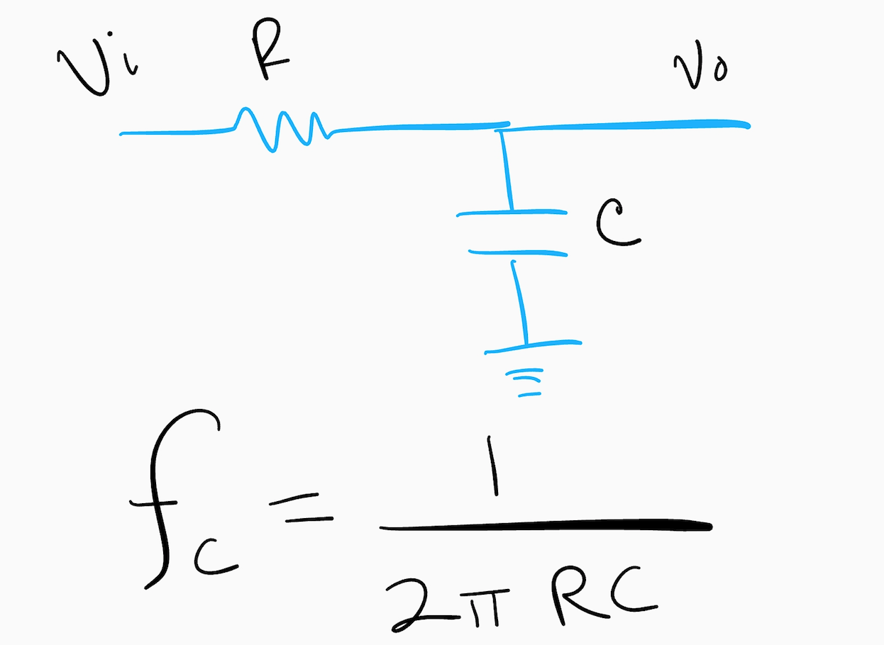 Analog signals typically are not ADC friendly, but they can be with some relatively simple circuitry such as a low pass filter and amplifier. The goal is to have the analog signal cover the entire range of the ADC. For example, if your input goes from 0V to 1V and your ADC measures from 0V to 3V, you will need to amplify the input to take full advantage of the ADC. Voltage scaling seems easy enough but you also need to make sure the frequencies you are measuring are low enough for your sample rate which is where filtering comes in.
A Low Pass Filter to Avoid Aliasing
For starters, it is important to understand how your sampling frequency impacts the digital version of your signal. If the sampling frequency is too low and the signal is changing too fast, the digital data will not accurately represent the analog data. So, you need to use a low pass filter to get rid of the signals that are changing too quickly. The circuit above shows a simple low pass circuit filter. The cutoff frequency is the point where less than half the power from the signal gets through. You want to choose values of R and C such that the cutoff frequency is less than half the sampling frequency (see Nyquist sampling frequency for proof).
Signal Scaling
If your signal voltage is too large, you can use a couple of resistors to make it smaller. If your signal is too small you will need to amplify it.
Voltage Divider
Using a couple of resistors to divide the voltage is called, of all things, a voltage divider. It is really simple to implement. The following diagram shows how.
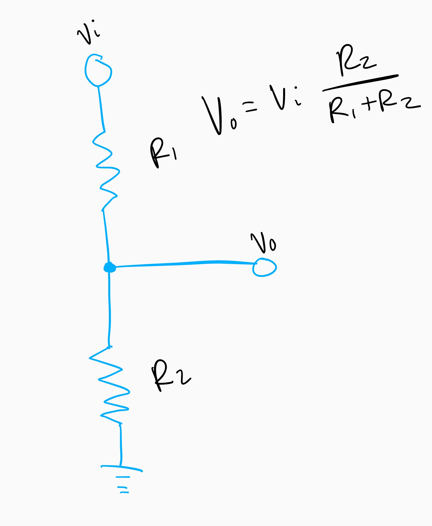
One item of caution is the values you use. Typically, an ADC will use a tiny amount of current and if the voltage divider resistor values are too large, it will make the reading inaccurate. Values in the kilo-ohms to tens of kilo-ohms are usually OK. If you need to use larger values, you can use a unity gain amplifier to make sure the current drawn by the ADC doesn’t adversely affect the reading.
Amplifier
If the signal is too small, you can amplify it using an op-amp. Two popular configurations are the inverting and non-inverting amplifiers. Depending on the signal, you might want to center the output midway through the ADC so that you don’t get negative values. You do that by adding a voltage divider on the static op-amp terminal.
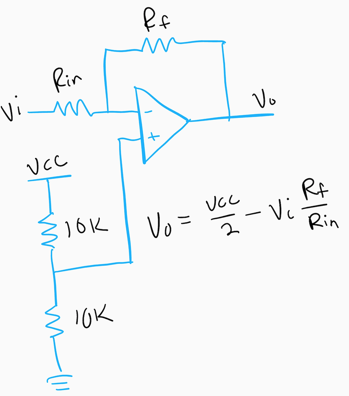
When selecting an op-amp, be sure to select a rail-to-rail op-amp. Otherwise, the op-amp output will not be able to swing the full range of the ADC input.
Putting It All Together
For filtering and stepping down a voltage using a divider, you can use the following circuit.
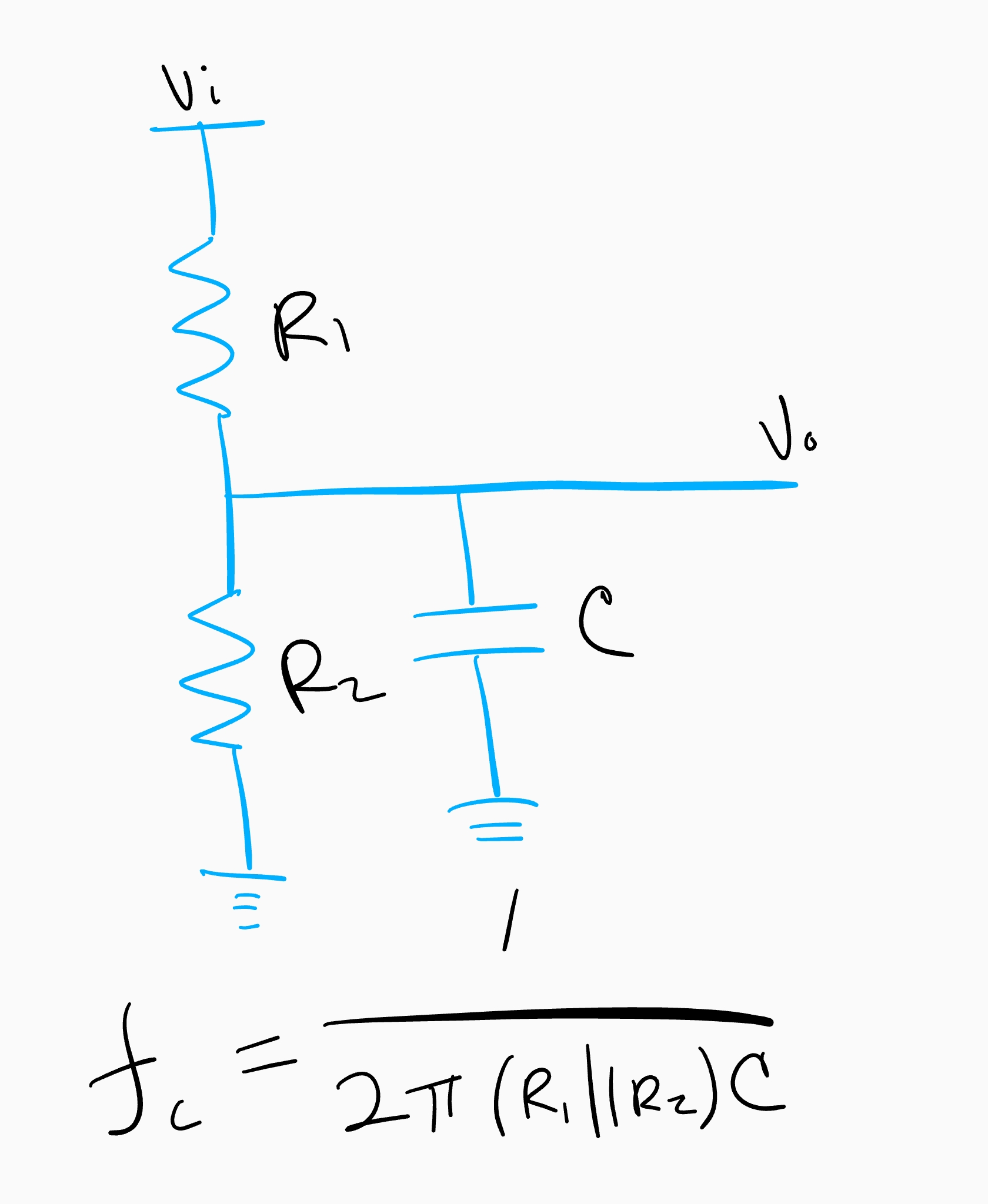
The cutoff frequency is calculated using the parallel combination of R1 and R2 along with C.
For amplifying smaller signals, you can use the following circuit.
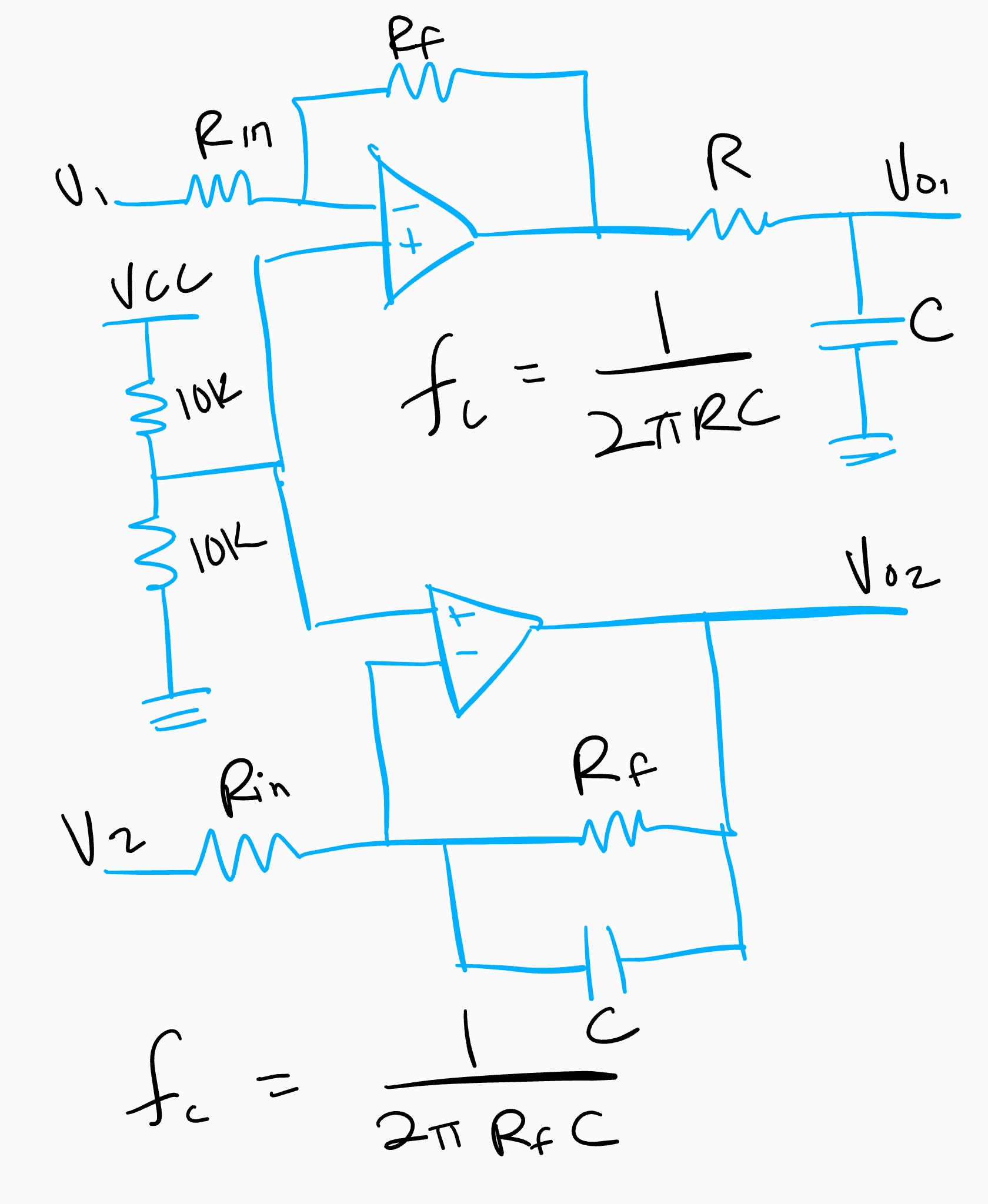
The top circuit is filtered using a passive filter while the bottom part uses an active filter. They both have the same cutoff frequency, but the active filter does a better job at attenuating frequencies that are above the cutoff.
